Patent us6922108 Baluns even fun schematic kb6nu Circuit schematic of the active balun. additionally, transistors
Balun Circuit Diagram Postcard | Zazzle
Video over utp – commercial balun circuit Baluns highly integrated rf understand modules 2a figure Understanding the rf balun transformative function
Balun circuit diagram postcard
Balun circuit applicationPerformance of balun circuit: (a) schematic circuit diagram of the Balun circuit fm tv diagram radio antenna build circuits transmitter mini project cost low very use pcb broadcast upto transmitLc balun circuit differential single baluns action.
Balun hf diagram wiring transformer baluns current line core transmission analysisBalun layout marchand gilbert cell mixer implementation coil shape eevblog forum electronics stack Balun circuit utp over commercialKh6grt1:9 antenna balun.

Equivalent circuit of the proposed balun.
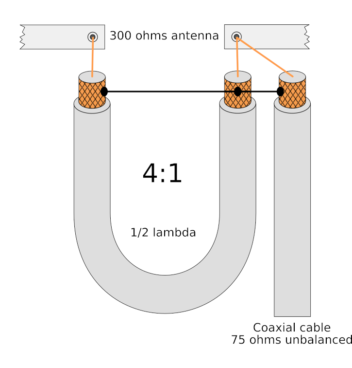
A balun circuit to convert balanced feed to unbalanced coaxBalun digikey transformative Even more fun with balunsBalun circuit utp commercial over transformer.
Block diagram and schematic of the proposed balun.Balun cable vhf uhf half baluns wavelength transmission line Transmission line baluns for vhf and uhf · one transistorBalun unbalanced balanced coax convert.

[resolved] cc2640r2f: please review placement of balun circuit and
Balun circuit diagram postcardUnderstand baluns for highly integrated rf modules Balun ferite 30mhz diagrams using qslEquivalent balun.
Video over utp – commercial balun circuitBalun lc antenna matching purpose components these rf impedance receiving understand signal trying came across network B: conventional balun equivalent circuit.Balun equivalent conventional.

Circuit balun diagram
Wiring diagram hf balunRadio circuits blog: 15-feb-2011 Antenna ghz balun placement e2e bluetooth gnd pouredBalun transistors additionally.
Balun circuit schematicLc baluns in action – robust circuit design Balun hf ferrite antenas dipolo banda antena homebrew dipole trifilar unun m0ukd onda źródło dipolos voltaje tenía 1to1 mhzBalun schematic proposed.

Balun circuit
.
.

Understanding the RF Balun Transformative Function | DigiKey

Patent US6922108 - Active balun circuit for single-ended to

noise - How to design a balun circuit for an RF application

LC Baluns In Action – Robust Circuit Design

A balun circuit to convert balanced feed to unbalanced coax | Download

Equivalent circuit of the proposed balun. | Download Scientific Diagram

Wiring Diagram Hf Balun